The PDB organizes the distribution of the power from the battery into various boards and devices around the rover. The PDB is separated into 7 channels with 3 different voltages that it outputs across 19 terminals. The PDB receives 24V in XT90 form from the BMS. The PDB stacks the converters on a tray to save the horizontal space it takes up in the enclosure.
Terminology
- Channel: a means for power to flow through, usually grouped by converter
- Converter: a module that converts one voltage to another, usually a buck or boost type
- Buck converter: a module that turns a higher input voltage into a lower output voltage
- Boost converter: a module that turns a lower input voltage into a higher output voltage
- Terminal: a place for a single device or module to connect into to get power
- Power: rate of energy transfer (watts)
Channel Overview
The channels are organized so that major devices have their own channel. The channels are listed in the following format: Purpose | Voltage | Connection type
- Light Board |12V | 5x1 5mm spaced terminal block
- Arm Board | 1x12V | Single XT30
- Fan Board, Orin | 3x1 5mm spaced terminal block
- Extra #1 | 12V | 3x1 5mm spaced terminal block
- Translator, Ethernet Switch | 5V | 3x1 3.5mm spaced terminal block
- Extra #2 | 5V | 3x1 5mm spaced terminal block
- Antenna | 24V | Single XT30
Future Improvements
- Integrate converters into the PDB instead of using modules
Bill of Materials
| Supplier | Part No | Quick Desc | QTY |
|---|---|---|---|
| Droking | DROK 090066 | (17-35V) to (12V) 20A Buck, 240W | 4 |
| DROK 090581 | (9-35V) to (5V) 5A Buck, 25W | 2 | |
| DROK 090598 | (10-22V) to (24V) 3A Boost, 72W | 1 | |
| Digikey | FUSE_3544-2 | Fuse Holders | 10 |
| 0297003.WXNV | 3A Fuse | 5 | |
| 0297015.WXNV | 15A Fuse | 5 | |
| 0297020.WXNV | 20A Fuse | 5 | |
| 0297010.WXNV | 10A Fuse | 5 | |
| JE2835APA-N-0001A0000-N0000001 | Power Indicator LED | 10 | |
| 1101A4CQEA | Sliding Switch | 20 | |
| DZDH0401DW-7 | Ideal Diode Controller | 10 | |
| FDS6681Z | Ideal Diode PMOS | 10 | |
| PHOENIX_1729160 | 1x6 Screw Terminal (5.08mm pitch) | 2 | |
| PHOENIX_1984659 | 1x6 Screw Terminal (3.5mm pitch) | 2 | |
| PHEONIX_1729092 | 1x10 Screw Terminal (5.0mm pitch) | 1 | |
| HV732HTTE1004F | 1M Ohm Resistor for Ideal Diode | 10 | |
| RMCF2010JT100K | 100K Ohm Resistor for Ideal Diode | 10 | |
| RMCP2010FT20R0 | 20 Ohm Power Indicator Resistor (High Current Side) | 10 | |
| RC2010JK-07100RL | 100 Ohm Power Indicator Resistor (Low Current Side) | 10 | |
| RC2010JK-07200RL | 200 Ohm Power Indicator Led Resistor | 10 | |
| FIT0588 | XT90 Vertical Connector Pair | 1 | |
| FIT0586 | XT30 Vertical Connector Pair | 16 |
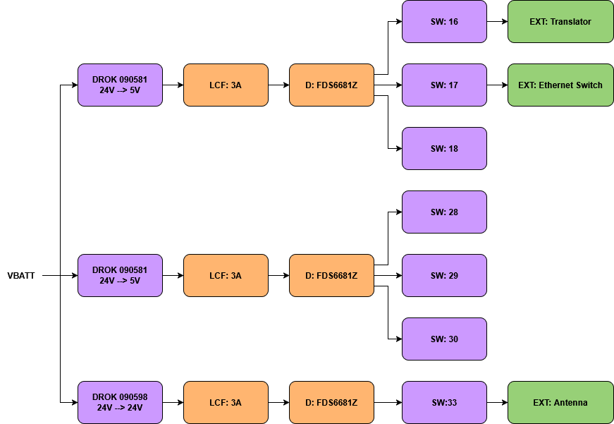
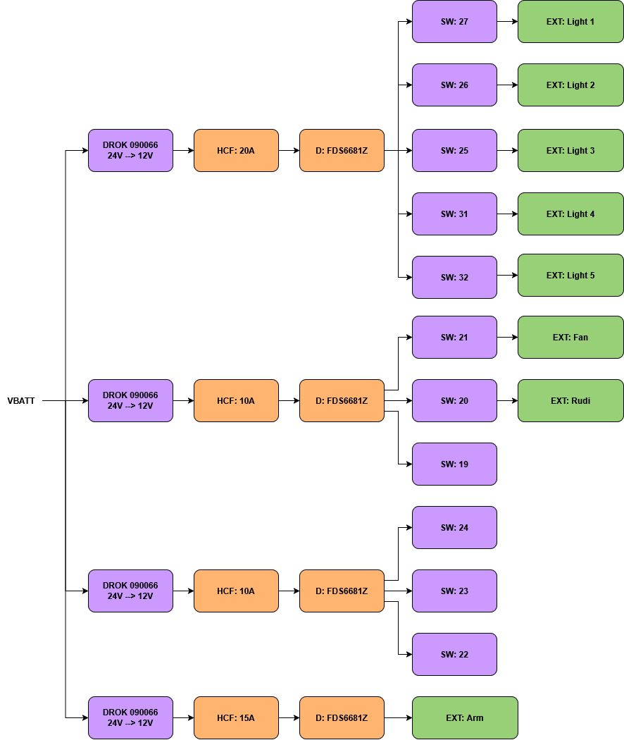
Block Diagram
Low Power
High Power
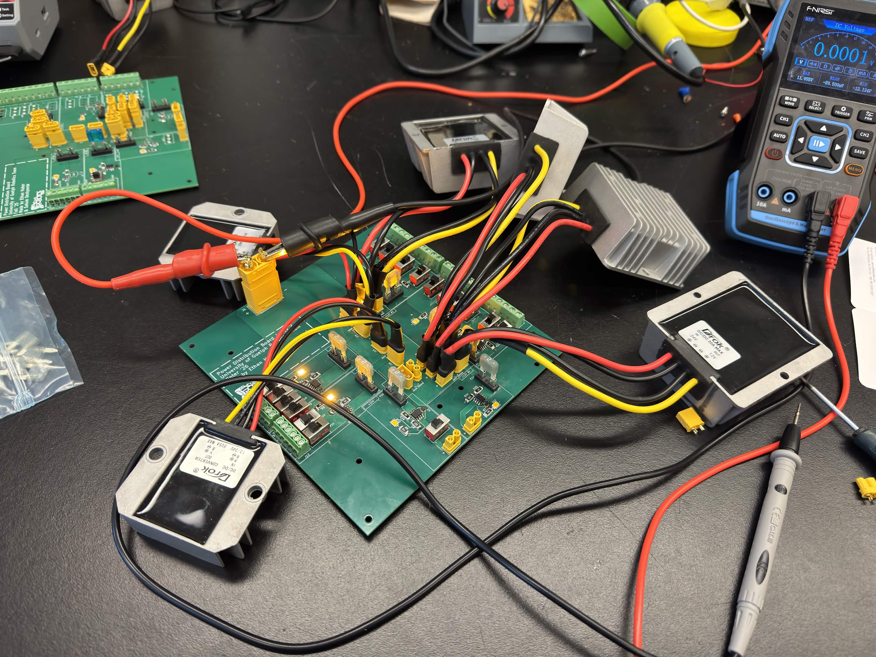
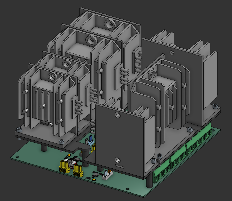
Gallery
CAD model isometric view.
Testing the second revision of the PDB.